Inspecting traffic sent to and received from the Internet
In this article:
Inspecting traffic sent to and received from the Internet#
The transit gateway can be used to inspect traffic between VPCs and the Internet.
Hint
It is recommended that you first read the tutorial for interconnecting two VPCs in order to understand, through a simple example, which path the traffic follows from the source to the destination.
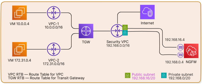
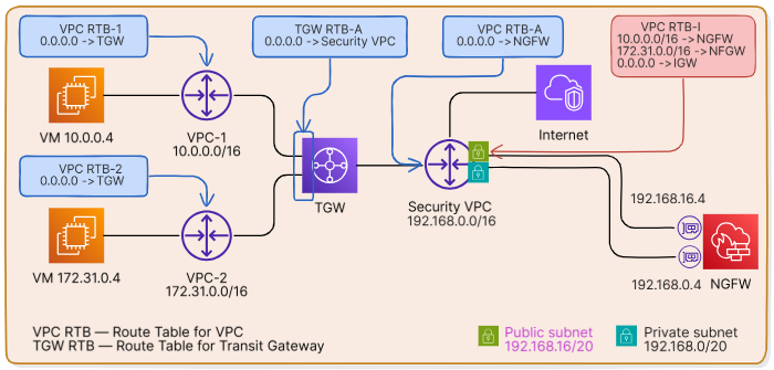
In the example at hand, all traffic between two VPCs – vpc-1 (10.0.0.0/16) and vpc-2 (172.31.0.0/16) – and the Internet is forwarded for inspection to a virtual security appliance (NGFW) in the third VPC (Security VPC) – vpc-s (192.168.0.0/16), which must be connected to the Internet (i.e. have an Internet gateway).
The instance with NGFW has two network interfaces attached: 192.168.0.4 in the private subnet 192.168.0.0/20 for communication with the VPCs and 192.168.16.4 in the public subnet 192.168.16.0/20 for communication with the Internet. An Elastic IP address is associated with the interface 192.168.16.4 for Internet access.
Subnets in vpc-1 and vpc-2 are associated with the main route tables of these VPCs – vpc-rtb-1 and vpc-rtb-2, respectively. Attachment subnets in the vpc-s are associated with the route table vpc-rtb-a. The private subnet 192.168.0.0/20 , to which the NGFW interface 192.168.0.4 is attached, is associated with the route table vpc-rtb-s. And the public subnet 192.168.16.0/20, to which the NGFW interface 192.168.16.4 is attached, is associated with the route table vpc-rtb-i.
Additionally, the transit gateway attachments to vpc-1 and vpc-2 are associated with the default association route table – tgw-rtb-a, and the transit gateway attachment to vpc-s is associated with the default propagation route table – tgw-rtb-p.
Important
In this scenario, to provide access via an Elastic IP address, you need to:
create a network interface in a public subnet that is connected to the NGFW;
allocate an Elastic IP address and associate it with the created network interface;
associate the private IP address of the network interface with the NGFW as an alias or configure Proxy ARP for it;
specify a NAT rule on the NGFW to forward traffic, targeted to this private IP address, to the private IP address of the target instance.
The general procedure is as follows:
set up routing from vpc-1 and vpc-2 to the Internet through the transit gateway;
set up routing to vpc-s on the attachments to vpc-1 and vpc-2 to forward traffic to the vpc-s for inspection;
set the route to NGFW in the route table of the attachment subnets in vpc-s;
set return route from vpc-s to vpc-1 and vpc-2 via the transit gateway;
set up routing on the attachment to vpc-s to route traffic to
vpc-1andvpc-2.
Create a transit gateway#
Note
The gateway will be created along with a default association route table tgw-rtb-a, while a default propagation route table tgw-rtb-p will be created separately and then associated with the transit gateway attachment to vpc-s.
Go to Interconnect Transit gateways and open the subsection of the same name.
Click Create.
Clear the checkbox Create route table and set it as default for::
route propagation.
Click Create to create the gateway.
Create attachment subnets#
In each availability zone, it is recommended to create an attachment subnet to which the transit gateway will be attached. If a subnet with instances is directly attached to a transit gateway, traffic from the gateway will flow to the instances directly and thus bypass a Network ACL. With an attachment subnet, traffic between the transit gateway and other subnets in this VPC always passes through the virtual router of the VPC and is therefore filtered by the Network ACL.
Note
Security group rules apply to the traffic on network interfaces in any case, even if the instance is located in the attachment subnet.
The attachment subnet is not recommended for placement of other resources, because it is intended only for communication with the transit gateway. Therefore, to use the least address space, the smallest possible IP subnet (/28) can be allocated as an attachment subnet.
Go to Virtual machines Networking Subnets and click Create.
In the subnet dialog window, set the following parameters:
vpc-1.(Optional) Name tag.
Subnet address
10.0.255.0/28.Availability zone to which the transit gateway should be attached.
If you need to set additional tags, go to the next step by clicking Add tags.
After setting all the required parameters, click Create subnet.
If there is only one availability zone in the region, create, in a similar way, the subnet 172.31.255.0/28 in vpc-2 and the subnet 192.168.255.0/28 in vpc-s.
If there are three availability zones in the region, create, in a similar way, the subnets 10.0.255.16/28 and 10.0.255.32/28 in the remaining availability zones in vpc-1, the subnets 172.31.255.0/28, 172.31.255.16/28 and 172.31.255.32/28 in the three availability zones in vpc-2 and the subnets 192.168.255.0/28, 192.168.255.16/28 and 192.168.255.32/28 in the three availability zones in vpc-s. The value of 255 in the third octet of the attachment subnet addresses is chosen to ensure that the VPC address space remains cohesive, contiguous, and sufficient for accommodating subnets with instances.
You can choose the number of availability zones where you are going to create subnets: one, two or three. However, for production infrastructures, we recommend creating attachment subnets in all availability zones beforehand, as you won’t be able to change them later, but have to create the transit gateway infrastructure from scratch again.
Create attachments#
Attachments must be created in each of the attached VPCs (see about connecting transit gateways).
When creating the first attachment, you can specify subnets in one or more availability zones at will. However, when creating another attachment, you must specify subnets in the same availability zones as for the first one.
Important
We recommend attaching the transit gateway to all availability zones to optimize the path for other traffic so that it is routed directly between the corresponding availability zones in different VPCs.
Note
Once created, the attachment cannot be associated with another subnet.
Go to Interconnect Transit gateways Attachments.
Click Create.
In the window that opens, set the following parameters:
The Name tag to identify the attachment, for example,
vpc-1(optional).The transit gateway you have created.
vpc-1.The attachment subnets in
vpc-1, to which the transit gateway will be attached.10.0.255.0/28;10.0.255.16/28;10.0.255.32/28.
In each of these subnets, a virtual interface will be created for attachment.
Click Create to create the attachment.
Similar attachments must be created for vpc-2 and vpc-s.
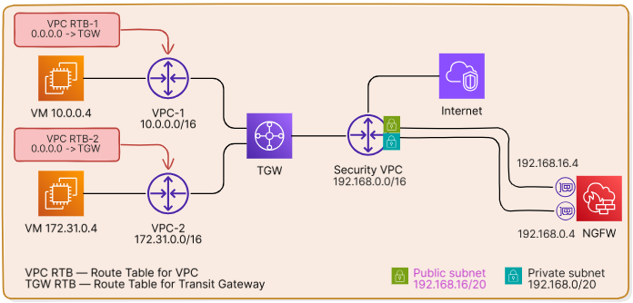
Configure Internet routing via transit gateway#
In vpc-1 and vpc-2, set up a route to the Internet via the transit gateway. Below it is assumed that all VPC’s subnets, from which traffic must be forwarded to the Internet, are associated with the main route table of this VPC – vpc-rtb-1 and vpc-rtb-2, respectively. If any subnet has another route table associated, then to make it forward traffic to the Internet, a route via the transit gateway must also be added to that table.
Go to Virtual machines Networking Route tables.
In the resource table, select the main route table of
vpc-1and click on the route table ID to go to its page.Open the Routes tab and click Add.
In the dialog window:
In the Network field, specify the target subnet
0.0.0.0/0.In the Gateway Type field, select Transit Gateway.
In the Gateway field, select the created transit gateway.
Click Add to create the route.
For
vpc-2, repeat steps 3-5.
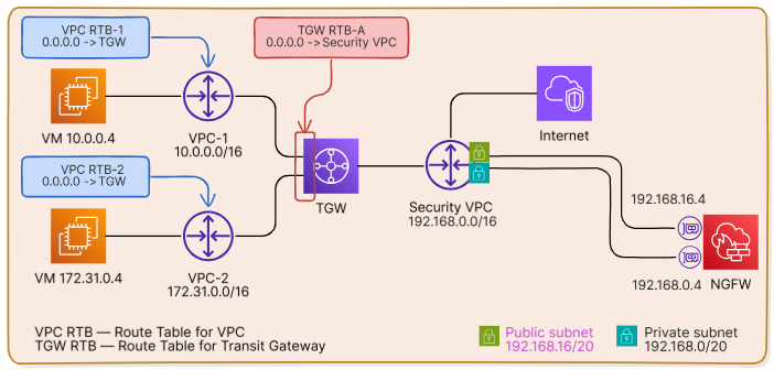
In tgw-rtb-a set up a route to vpc-s#
The tgw-rtb-a route table, created together with the transit gateway, was selected as the default association route table. It is automatically associated with all transit gateway attachments to VPCs (including the transit gateway attachment to vpc-s, but it will be subsequently associated with another route table – tgw-rtb-p). For the transit gateway to forward traffic to vpc-s for inspection, set up routes to vpc-s.
Go to Interconnect Transit gateways Route tables.
In the resource table, select the transit gateway route table
tgw-rtb-aand click on the route table ID to go to its page.In the Routes tab click Add.
In the dialog window:
In the Network field, specify
0.0.0.0/0for all outbound traffic to be forwarded tovpc-s.In the Attachment field, select the attachment through which
vpc-sis attached to the transit gateway.
Click Create.
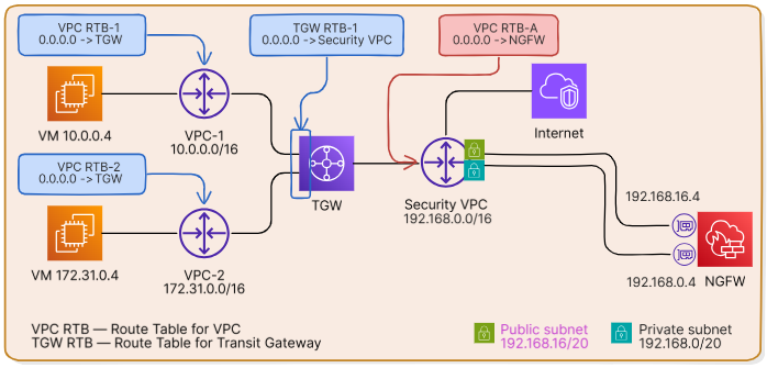
In vpc-rtb-a set up a route to the NGFW#
All traffic coming from vpc-1 and vpc-2 to the attachment subnets in vpc-s must be forwarded to the NGFW at 192.168.0.4 for further inspection. To do this, create a separate route table vpc-rtb-a, associate it with the attachment subnets and set up a route to the NGFW in that table.
Go to Virtual machines Networking Route tables.
Associate the created route table with attachment subnets in vpc-s.
In the resource table, select the created route table and click on the table ID to go to its page.
Open the Routes tab and click Add.
In the dialog window:
In the Network field, specify
0.0.0.0/0.In the Gateway type field, select
Instance.In the Gateway field, select from the drop-down list the instance with interface 192.168.0.4, where the NGFW is running.
Click Add to create the route.
In vpc-rtb-i, set up routes to the Internet#
The NGFW connects to the public subnet 192.168.16.0/20 via the interface 192.168.16.4. For this subnet, you need to configure traffic routing to/from the Internet in the vpc-rtb-i route table.
Go to Virtual machines Networking Route tables.
Associate the created route table with the public subnet in vpc-s.
In the resource table, select the created route table and click on the table ID to go to its page.
Go to the Routes tab.
To route traffic to the Internet, click Add in the window that opens:
In the Network field, specify
0.0.0.0/0;In the Gateway type field, select Standard Internet gateway.
Click Add to create the route.
To inspect inbound traffic from the Internet to
vpc-1, click Add again and in the window that opens:in the Network field, specify
10.0.0.0/16;In the Gateway type field, select
Instance.In the Gateway field, select from the drop-down list the instance with interface 192.168.16.4, where the NGFW is running.
Click Add to create the route.
To inspect inbound traffic from the Internet to
vpc-2, click Add again and in the window that opens:In the Network field, specify
172.31.0.0/16.In the Gateway type field, select
Instance.In the Gateway field, select from the drop-down list the instance with interface 192.168.16.4, where the NGFW is running.
Click Add to create the route.
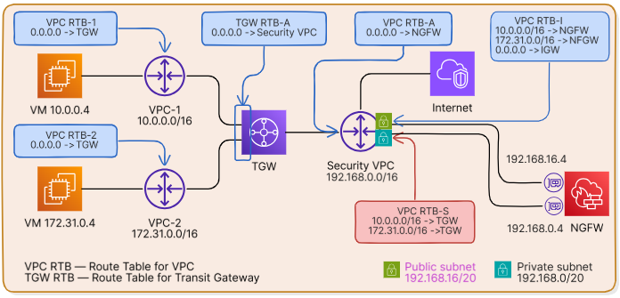
Set up return routes in vpc-rtb-s#
In the vpc-rtb-s route table associated with the private subnet 192.168.0.0/20, in which the NGFW interface 192.168.0.4 is placed, set up routes to vpc-1 and vpc-2.
Go to Virtual machines Networking Route tables.
Associate the created route table with the private subnet in vpc-s.
In the resource table, select the created route table in
vpc-sand click on the route table ID to go to its page.Open the Routes tab and click Add.
In the dialog window:
In the Network field, specify the target network in
vpc-1. In this example, this is the network10.0.0.0/16, which corresponds tovpc-1.In the Gateway Type field, select Transit Gateway.
In the Gateway field, select the transit gateway you are using.
Click Add to create the route.
For
vpc-2, repeat steps 3-5.
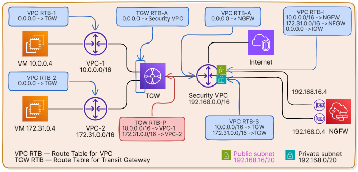
Set routing for the attachment to vpc-s#
To forward inspected traffic to target VPCs, configure the transit gateway route table tgw-rtb-p and associate it with the attachment to vpc-s. To automatically add routes to other VPCs, it is recommend to set this table as the default one for route propagation.
Go to Interconnect Transit gateways Route tables.
In the resource table, select the created route table and click on the table ID to go to its page.
In the Route propagation tab, click Enable route propagation. In the window that opens, select the transit gateway attachments to
vpc-1andvpc-2. Click Enable.Go to Interconnect Transit Gateways Transit Gateways and set the table as default for route propagation. Routes to all subsequently attached VPCs will be automatically added to this table.
Go to Interconnect Transit gateways Route tables and associate this route table with transit gateway attachment to vpc-s.
The created default propagation route table tgw-rtb-p will be associated with the attachment to vpc-s instead of tgw-rtb-a, a default association route table. Routes through the transit gateway to vpc-1 and vpc-2, as well as to all subsequently attached VPCs, will be installed in this table automatically.