Interconnection of several VPCs
In this article:
Interconnection of several VPCs#
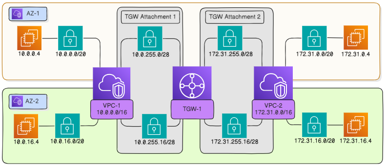
To interconnect two or more VPCs, you can use a transit gateway. The following example shows how to interconnect two VPCs, vpc-1 (10.0.0.0/16) and vpc-2 (172.31.0.0/16), in the same project. If necessary, you can attach VPCs from other projects (including those of other companies) to the transit gateway by providing access to the gateway.
The general procedure is as follows:
set routes in the transit gateway route table to attached VPCs;
set the route in route table of each VPC through the transit gateway to another VPC;
allow appropriate traffic, such as ICMP, in the security groups associated with the instances between which this traffic is to be transmitted.
Traffic flow example#
In this example, it is assumed that vpc-1 hosts a running instance with the address 10.0.0.4 in the subnet 10.0.0.0/20 in the availability zone az-1, and vpc-2 hosts a running instance with the address 172.31.16.4 in the subnet 172.31.16.0/20 in the availability zone az-2. It is also assumed that the instance 10.0.0.4 pings the instance 172.31.16.4. Finally, it is assumed that the subnet 10.0.0.0/20 is associated with the main route table vpc-rtb-1 for vpc-1 and the subnet 172.31.16.0/20 is associated with the main route table vpc-rtb-2 for vpc-2.
The instance 10.0.0.4 sends an ICMP echo request to the virtual router of
vpc-1at 172.31.16.4.The virtual router of
vpc-1checks the destination address against the route tablevpc-rtb-1associated with the subnet and routes the packet to the virtual interface of the transit gateway attachment to vpc-1` in the availability zoneaz-1.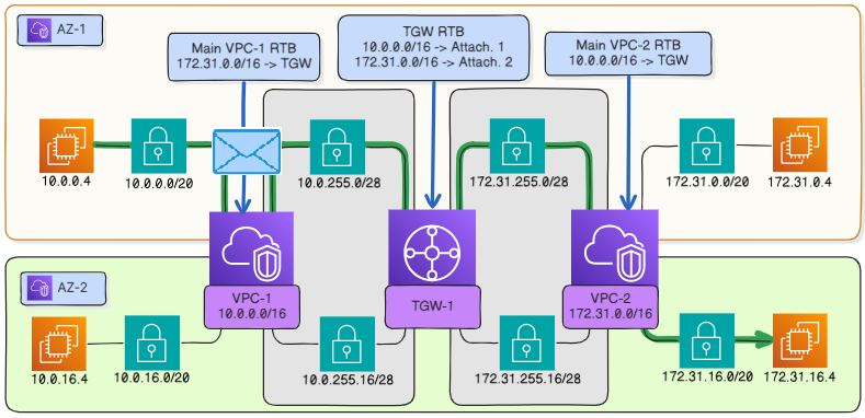
The virtual router of
vpc-1receives a packet destined for 172.31.16.4 and forwards it to the transit gateway attachment tovpc-1according to the route table.#The transit gateway forwards the packet to the virtual interface of the attachment to
vpc-2in the same availability zoneaz-1according to its route table.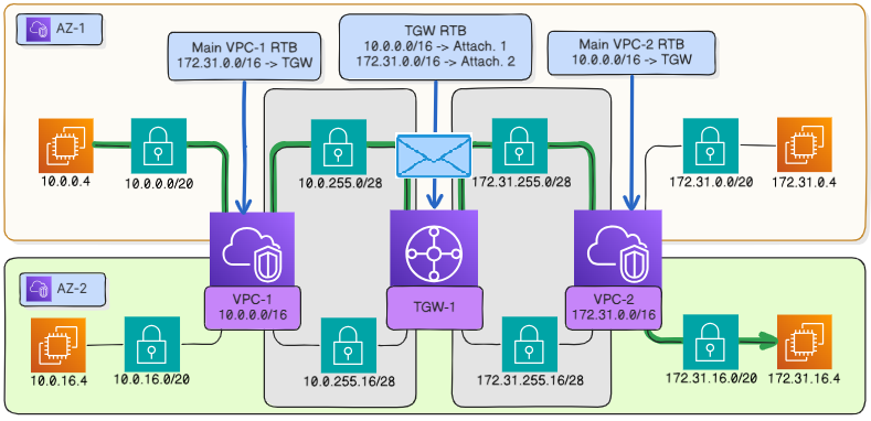
The transit gateway receives a packet destined for 172.31.16.4 from the attachment to
vpc-1and forwards it to the attachment tovpc-2, according to its route table.#The virtual router of
vpc-2forwards the inbound packet from the transit gateway to the subnet 172.31.16.0 in the availability zoneaz-2, where the instance 172.31.16.4 is placed.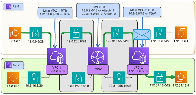
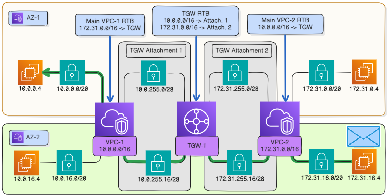
The virtual router of
vpc-2receives a packet destined for the instance in a subnet connected thereto.#The packet is delivered.
The echo packet goes back along a similar route from the instance 172.31.16.4 to the instance 10.0.0.4. However, the major portion of the route – to the attachment subnet in the vpc-1 – lies within the availability zone az-2.
Create a transit gateway#
Go to Interconnect Transit gateways and open the subsection of the same name.
Click Create.
Do not change the checkbox Create route table and set it as default for:
associations;
route propagation.
When selected, all new attachments are associated with the created default route table and route propagation from these attachments is enabled. This eliminates the need to manually configure static routes to each VPC in the transit gateway route tables.
Click Create to create the gateway.
Create attachment subnets#
In each availability zone, it is recommended to create an attachment subnet to which the transit gateway will be attached. If a subnet with instances is directly attached to a transit gateway, traffic from the gateway will flow to the instances directly and thus bypass a Network ACL. With an attachment subnet, traffic between the transit gateway and other subnets in this VPC always passes through the virtual router of the VPC and is therefore filtered by the Network ACL.
Note
Security group rules apply to the traffic on network interfaces in any case, even if the instance is located in the attachment subnet.
The attachment subnet is not recommended for placement of other resources, because it is intended only for communication with the transit gateway. Therefore, to use the least address space, the smallest possible IP subnet (/28) can be allocated as an attachment subnet.
Go to Virtual machines Networking Subnets and click Create.
In the subnet dialog window, set the following parameters:
vpc-1.(Optional) Name tag.
Subnet address
10.0.255.0/28.Availability zone to which the transit gateway should be attached.
If you need to set additional tags, go to the next step by clicking Add tags.
After setting all the required parameters, click Create subnet.
In a similar way, create the subnets 10.0.255.16/28 and 10.0.255.32/28 in the remaining availability zones (if they exist in the region) in vpc-1 and the subnets 172.31.255.0/28, 172.31.255.16/28 and 172.31.255.32/28 in the three availability zones (if they exist in the region) in vpc-2. The value of 255 in the third octet of the attachment subnet addresses is chosen to ensure that the VPC address space remains cohesive, contiguous, and sufficient for accommodating subnets with instances.
You can choose the number of availability zones where you are going to create subnets: one, two or three. However, for production infrastructures, we recommend creating attachment subnets in all availability zones beforehand, as you won’t be able to change them later, but have to create the transit gateway infrastructure from scratch again.
The choice of availability zones for attachment subnets affects the traffic route between the VPC and transit gateway. For example, if each of the attached VPCs has an attachment network in only one availability zone, traffic between subnets in other availability zones of these VPCs will be routed through that zone. However, if you create subnets in each zone, traffic will be routed along the shortest path.
Create attachments#
Attachments must be created in each of the attached VPCs (see about connecting transit gateways).
When creating the first attachment, you can specify subnets in one or more availability zones at will. However, when creating another attachment, you must specify subnets in the same availability zones as for the first one.
In this example, the attachments are created in two availability zones.#
Traffic can be exchanged between any subnets in these VPCs, not only those directly attached to the transit gateway — it is only necessary to set routes through the transit gateway in the route tables of these subnets.
Note
Once created, the attachment cannot be associated with another subnet.
Go to Interconnect Transit gateways Attachments.
Click Create.
In the window that opens, set the following parameters:
The Name tag to identify the attachment, for example,
vpc-1(optional).The transit gateway you have created.
vpc-1.The attachment subnets in
vpc-1, to which the transit gateway will be attached.10.0.255.0/28;10.0.255.16/28.
In each of these subnets, a virtual interface will be created for attachment.
Click Create to create the attachment.
Similar attachments must be created for vpc-2.
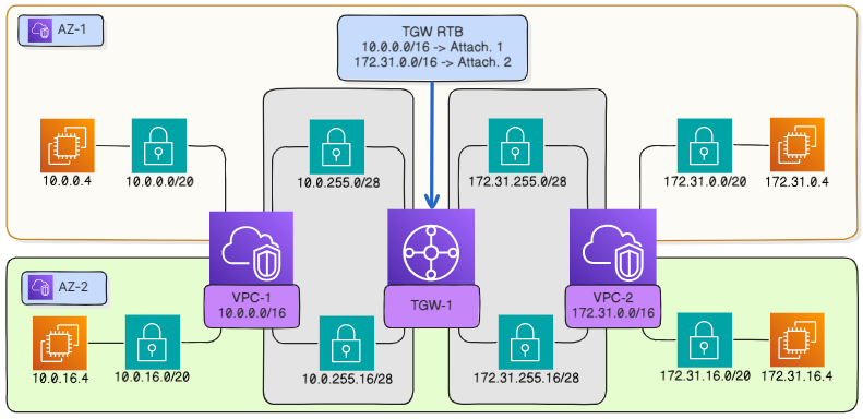
Specify routes in the transit gateway route table#
If you haven’t cleared the checkbox Create route table and set it as default for: route propagation for the default transit gateway route table, routes to vpc-1 and vpc-2 will be installed in it automatically. Otherwise, you will need to configure a route to each attached VPC through the appropriate attachments:
Go to Interconnect Transit gateways Route tables.
In the resource table, select the route table of the created transit gateway and click on the table ID to go to its page.
In the Routes tab click Add.
In the dialog window:
In the Network field, specify the network that corresponds to
vpc-1(10.0.0.0/16). You can specify the CIDR block of any subnet fromvpc-1if traffic must be forwarded only to it.Attachment, through which
vpc-1is attached to the transit gateway.
Click Create.
To set the route to
vpc-2, repeat steps 3-5.
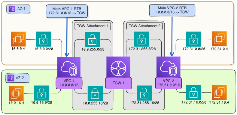
Specify routes in the VPC route table#
In each VPC, set a route to another VPC via the transit gateway. Below it is assumed that in a VPC all subnets from which traffic must be routed to another VPC are associated with the main route table of that VPC. If a different route table is associated with some subnets, then a route via the transit gateway must also be set in it for traffic to be transmitted from those subnets to another VPC.
Go to Virtual machines Networking Route tables.
In the resource table, select the main route table of
vpc-1and click on the route table ID to go to its page.Open the Routes tab and click Add.
In the dialog window:
In the Network field, specify the target network in
vpc-2. In this example, this is network172.31.0.0/16, which corresponds tovpc-2.In the Gateway Type field, select Transit Gateway.
In the Gateway field, select the created transit gateway.
Click Add to create the route.
For
vpc-2, repeat steps 2-4.
Enable required traffic#
For the traffic to flow between instances in different VPC, enable the appropriate protocol in the security groups assigned to those instances.
As an example, let’s say, you need to mutually ping instances in different VPCs. Here we assume that the default security group of a respective VPC is assigned to each instance.
Go to Virtual machines Security Security groups.
In the resource table, find the default security group for
vpc-1and click on its ID to go to the group page.On the Inbound rules tab click Add.
In the dialog window:
In the Protocol field, select ICMP.
For the Grant access option, select From network.
In the Network field, enter the subnet in
vpc-2, in which the instance resides, for example,172.31.16.0/20, as in the traffic flow example. Alternatively, specify a CIDR block for the entirevpc-2, in this case172.31.0.0/16.
For
vpc-2, repeat steps 2-4.
Check that everything is OK. From the instance in vpc-2, ping the internal IP address of the instance in vpc-1. Do the same for the instance in vpc-1.